Solar Bollard Lights
Solar bollards blend low-glare lighting with weatherproof protection designed for pathways, parks, and architectural perimeters. With integrated solar panels, high-impact protection (up to IK10), and sensors, they provide safe lighting for pedestrian spaces.
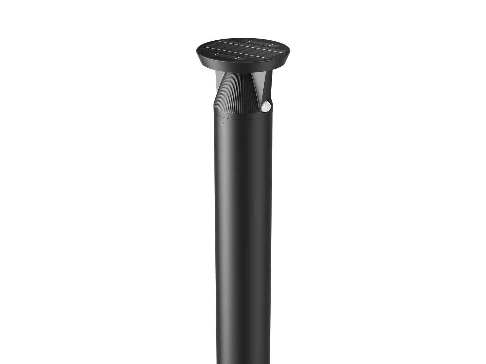

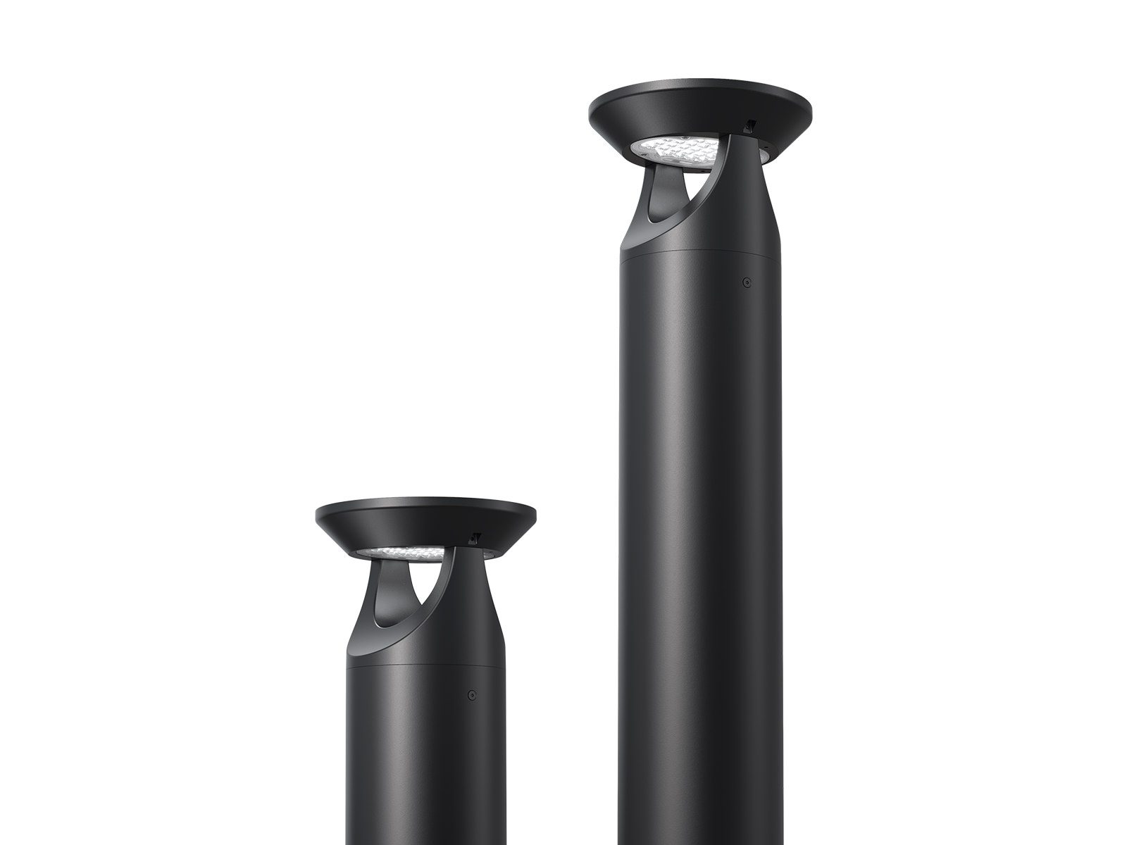
Solar bollard lights are luminaires that light a walking route at knee-to-waist height. Each unit carries its own panel, battery, controller, and LED, so a path can be lit without trenching through finished landscaping.
The core engineering challenge is not maximum lumen output, but ensuring optical coverage overlaps continuously, because a pathway is judged by its darkest gap, not its brightest spot.
Applications & Ideal Site Conditions
Bollards are used where the brief is wayfinding, edge definition, and visual amenity rather than high-level illumination.
Paths and trails
Pedestrian routes through parks, corporate campuses, and housing developments.
Plazas and gardens
Sites where a low-profile fitting enhances architecture and trenching through existing paving is cost-prohibitive.
Building perimeters and entrances
Forecourts and walkways where a continuous line defines the primary route.
Cycle paths
Shared routes requiring low-glare edge marking at a low mounting height.
Campuses and hospitality
High-end resort grounds and institutional walkways where daytime aesthetic integration matters.
Waterfront and wildlife sites
Sensitive shorelines and reserves where local regulations mandate full cutoff, amber output.
Light Levels & Uniformity Standards for Walking Routes
Pedestrian routes are specified in illuminance. Where a public route falls under EN 13201, the relevant set is the P classes, from P1 for high-activity pedestrian zones to P6 for low-volume paths.
The practical floor for safe navigation on any walking route.
Typical design range for commercial routes and campus pathways.
Overall uniformity (Emin/Eavg) — an average-to-minimum ratio of 3:1 on the walking surface.
Visual continuity depends on uniformity rather than average light levels. A route that is bright on average but patchy underfoot still fails the brief.
Spacing & Photometrics
Spacing determines project success, yet it is the metric most frequently estimated without calculation. Spacing is a system variable: it depends on mounting height, optical distribution, and target illuminance combined.
| Configuration | Optical distribution | Achievable spacing |
|---|---|---|
| 1 m bollard, specialised optic | Type II forward throw | Up to ≈ 9 m at 0.1 fc minimum |
| 1 m bollard, standard optic | Symmetrical | 3 m – 5 m |
| 450 mm bollard | Standard | ≈ 4.5 m |
Spacing must always be validated via a photometric layout for the target path width.
The “String of Pearls” effect
When fixtures are spaced too far apart, the route reads as bright pools separated by dark, an effect called the string of pearls or zebra banding. It is a safety problem before an aesthetic one, because alternating bright and dark is disorienting for pedestrians with low vision.
Tighten spacing, don’t boost lumens
More lumens brighten each pool without closing the gap between them, so the contrast worsens. Moving fixtures closer improves uniformity more effectively than upsizing every unit, and usually costs less than the larger panel and battery a higher output would demand.
Choosing a layout
Single-sided run
- One continuous run along a single edge of the path.
- Uses a Type II forward-throw optic to push light along the route.
- Lowest fixture count for narrow routes.
Staggered layout
- Fixtures alternate from side to side along the route.
- Improves uniformity across the full path width.
- Achieves better results without requiring tighter spacing.
Optical distribution selection
Type II
- Throws the beam along the route, where people actually walk.
- Supports wider spacing at the same minimum illuminance.
- Less spill to the sides of the path.
Type V
- Spreads output evenly in every direction.
- Sends a good share of its light sideways, to places where nobody walks.
- Better suited to open plazas than to linear routes.
Optical Control: Managing Glare and Light Trespass
A pedestrian passes a bollard at the same height the light sits, which makes comfort glare the governing concern rather than the disability glare that matters to a driver. Full cut-off construction and a diffusing lens are what keep a fitting comfortable to walk beside.
Rating by BUG and lighting zone
The BUG system (backlight, uplight, glare) is the usual measure, and outdoor lighting zones run from LZ1, where little spill is tolerated, to LZ4 in town centres. A bollard should rate low on all three, because what spills from a low fitting is seen directly by the people it serves.
Keeping light where it belongs
A run along a boundary or shoreline can put light where it is not wanted. Meeting those limits is mostly optical: shielding, low colour temperature (3000 K or below), and amber output around 590 nm on sensitive coastlines.
Maximizing Autonomy with Motion Sensing and Smart Controls
A road is lit for traffic that does not stop. A path usually is not. Footfall on a walkway, campus route, or park trail is intermittent with long inactive stretches, which is what makes motion-triggered control effective here in a way it is not on a carriageway.
Profile the footfall
Path use is intermittent with long inactive stretches — the precondition that makes sensing worthwhile.
Choose PIR over microwave
PIR (Passive Infrared) sensors are typically preferred in heavily landscaped areas to prevent false triggering from windblown foliage.
Hold low, lift on detection
The common arrangement holds the fitting at a low ambient level and lifts it to a higher output on detection.
Fine-tune on site
Timed dimming schedules and handy remote controllers give complete flexibility to match local site requirements.
Reduction in nightly energy use against running at full output from dusk to dawn.
Mechanical & Environmental Requirements
A solar bollard lives where the damage happens: within reach of a deliberate kick, in the path of grounds equipment, and low enough to collect what the weather deposits.
Impact and ingress
IK08 is a sensible minimum on a public route and IK10 the rating to specify where vandalism or vehicle contact is likely.
IP65 is the floor, rising to IP66 or IP67 where the fitting sits in irrigation spray and standing water. Including a pressure-equalizing breather membrane (such as a Gore vent) prevents internal condensation caused by ground-level thermal shifts.
Coastal and de-iced sites
Salt attacks housing and fixings, so the corrosion class should match the location, often meaning marine-grade aluminium or a specified coating.
FAQ
It depends on mounting height, optic, and target illuminance together, so there is no single figure. Confirm layout metrics with a photometric simulation for the actual path width.
Bright pools separated by dark stretches, which appears when bollards are spaced too far apart. Also called zebra banding.
They suit them well, because footfall on a path is intermittent.
It can, and this risk is specific to ground-level fittings, because a pole-mounted panel sheds snow that a low one collects.
Most anchor to a small concrete footing or a direct-burial ground anchor, with bolt-down fixings where the unit sits on existing paving.